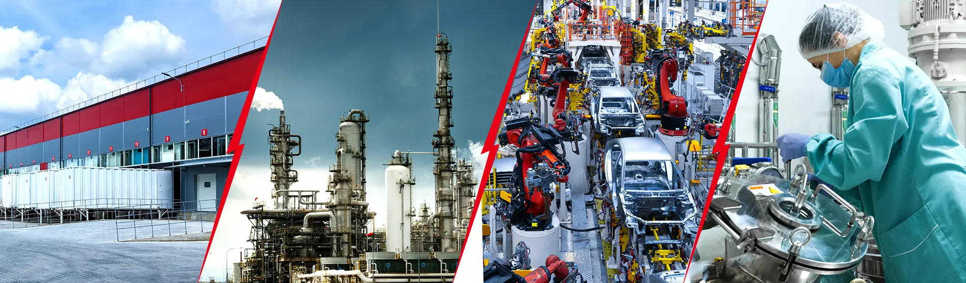
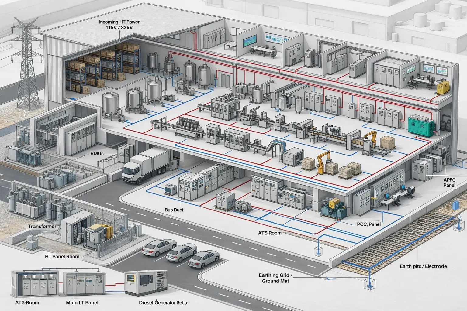
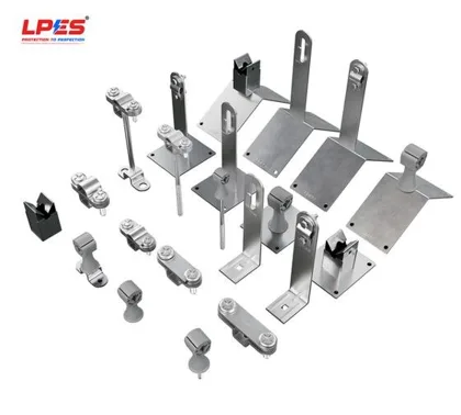
The problemLightning protection with one specialist, earthing with another, surge protection in a separate package. The risk crosses those boundaries and nobody owns the gap.
Every facility depends on an electrical system that must work as a whole, yet its protection is often divided between specialists. LPES brings Lightning Protection, Power Protection, Earthing Protection and Surge Protection together under one engineering responsibility. We call it Lightning to Load.
Lightning protection systems built to IEC 62305-3 and IS/IEC 62561
Earthing and bonding to IS 3043:2026, IEEE 80 and CEA Regulations 2023
Surge protective devices for power, SCADA, PLC, data and signal lines to IEC 61643-11 and IEC 61643-21
Electrical safety for modern commercial infrastructure
The problemSensitive electronics are built to withstand about 1.5 kV. Lightning induces several times that in cables hundreds of metres from the strike.
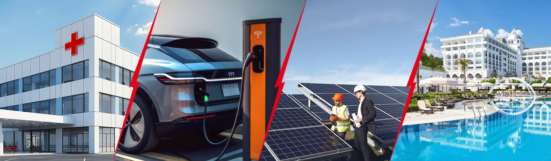
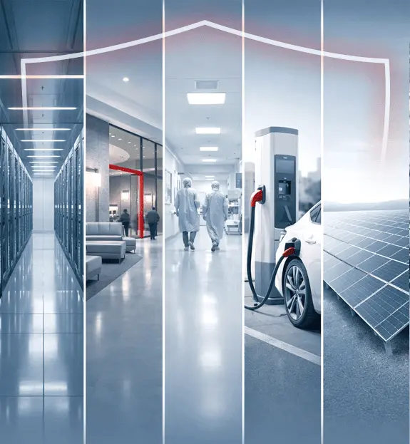
Hospitals, EV charging hubs, solar rooftops, hotels and office towers run on electronics that fail at a few hundred volts of surge. LPES protects the structure, the incoming services and the equipment as one coordinated system, so the building stays open.
External lightning protection designed by the rolling sphere and mesh methods
Surge protection coordinated from the main LT panel to the final distribution board
Earthing audits and periodic testing, with every reading recorded
Where a lightning strike is a process-safety event
The problemIn a hazardous area a spark across an unbonded gap is an ignition source, and a tripped safety loop shuts the unit down.
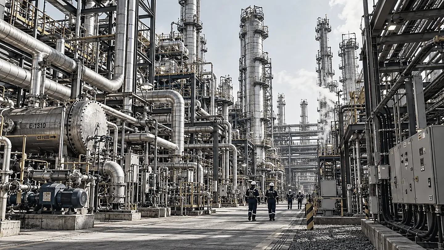
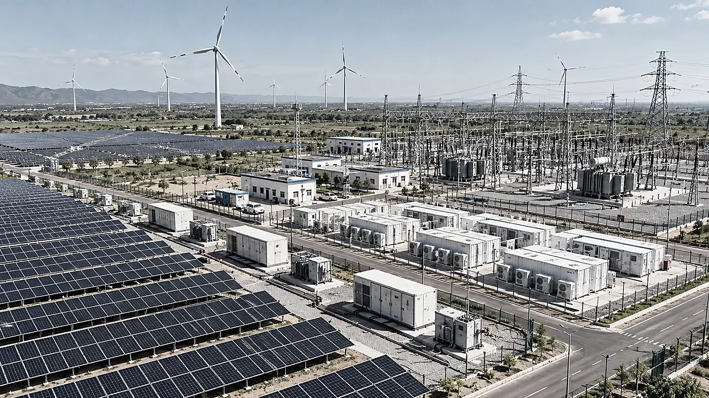
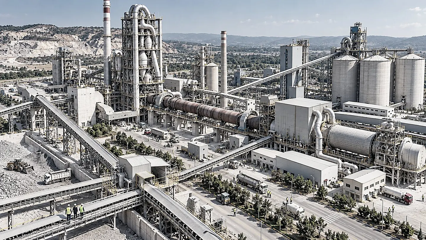
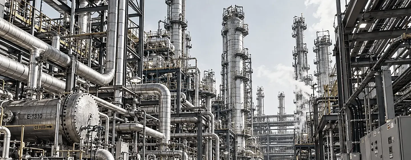
On a refinery, a cement line or a solar park, lightning does more than damage equipment. It starts fires, trips safety loops and stops production for days. LPES engineers the air termination, the earth grid, the bonding and the surge protection together, and places every component against the hazardous-area drawing.
Isolated air termination and masts for tank farms, vents and analyser houses
Static earthing, flange bonding and Ex isolating spark gaps
Substation and plant earth grids designed for step and touch voltage
The problemSignalling, IT and SCADA cables run for kilometres outdoors and carry every surge straight into the control room.
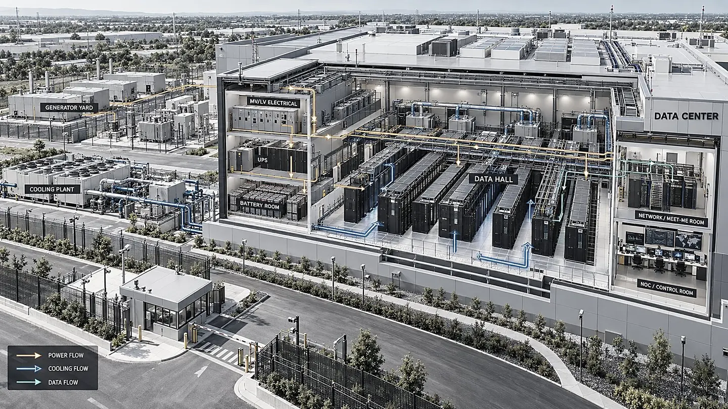
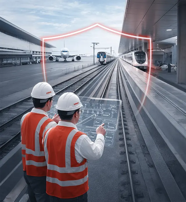
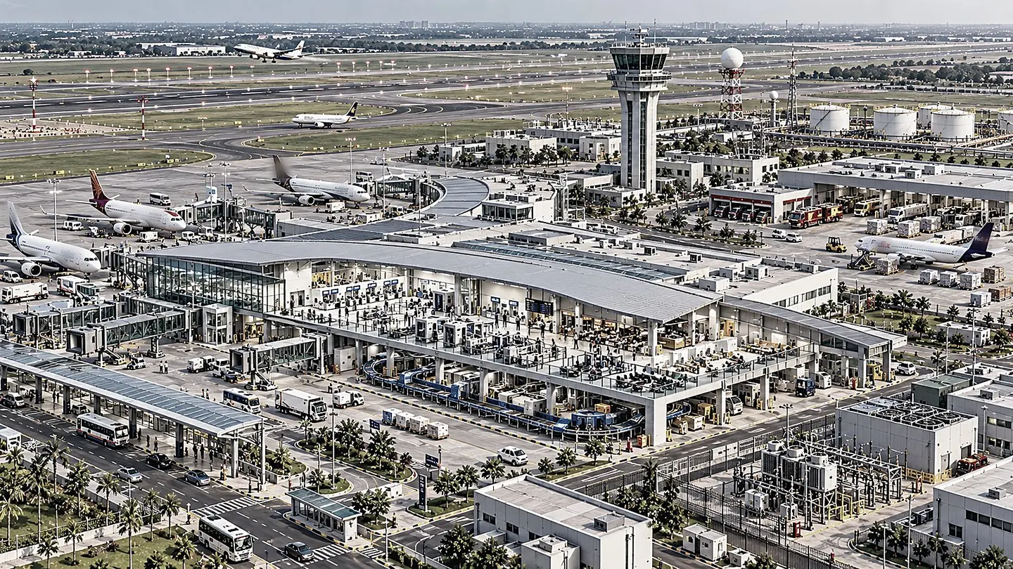
A data hall, an airport terminal and a railway signalling room share one requirement: no interruption. LPES builds the meshed bonding network, the coordinated surge protection and the monitored earthing that keep them running through the monsoon.
Meshed bonding networks and telecom bonding backbones for data halls
SPDs for power, signalling, CCTV, PoE and RF lines at every zone boundary
Lightning strike counters, earth monitoring and SPD status signalling
Safety reacts after the fault. Protection acts before it.
The differenceSigns, PPE and procedures respond once something has gone wrong. They are the last line, and they depend on people.
Protection is engineered in advance. The strike is intercepted, the fault current has a path, step and touch voltage is limited, the surge is diverted and the supply disconnects before a person or a machine is exposed. Select a pillar on the drawing to compare the two.
Electrical risks cross those boundaries. Responsibility should connect them. Four reasons the gaps matter.
4packages, no owner of the gaps
Protection is bought in separate packages
Lightning protection goes to one specialist, the power study to another, earthing to the civil contractor and surge protection to the panel builder. Each package can pass its own inspection while the connections between them are left to chance: the down conductor that never reaches the earth ring, the SPD with no short path to the earthing bar.
Source: LPES brand story: electrical risks cross those boundaries, responsibility should connect them
What LPES does about it
One engineering responsibility across all four pillars, with every interface drawn, owned and tested.
The national lightning location network recorded 4.77 million cloud-to-ground strikes over India in 2019 and 6.33 million in 2020. The Ministry of Earth Sciences told the Lok Sabha that lightning activity has risen over the past two decades. A building assessed ten years ago is exposed to more strikes today, and the protection level chosen then may no longer be enough.
IEC 62305-2 treats every flash within 500 m of a structure, and every flash to or near an incoming line, as a source of damage to the systems inside. Drives, PLC cards, CCTV and servers fail from the surge induced in their cables, often with no visible strike at all.
Source: IEC 62305-2, sources of damage S2, S3 and S4
What LPES does about it
Surge protective devices coordinated at every point where a power, data or signal cable crosses into the building.
IEEE 80 puts the current a 50 kg person can tolerate for half a second at about 164 mA. A corroded joint, a missing protective conductor or an untested earth pit lets touch voltage rise beyond that the moment a fault occurs, and nothing shows it beforehand.
Source: IEEE 80-2013, tolerable body current 0.116/√t
What LPES does about it
Earthing designed for the fault level and soil, protective earthing conductors on every item, and test records you can show.
Lightning, surges and earth faults move through the whole installation. One working plant in 3D, turning slowly. First the red pulses show how lightning, surge and fault current travel through it. Then the view switches to the LPES system: air termination, SPDs on power and data lines, bonding, step and touch protection and a verified earth fault loop. Select any numbered point.
Drag to rotate
How lightning, surge and fault current travel between the points
1Lightning
Roof and rooftop equipment
The problem
The roof is the first thing a strike meets. Without air termination the current enters through rooftop units, vents and cable trays.
What LPES does
A mesh and rod air-termination system sized by the rolling sphere method, with down conductors at the spacing IEC 62305-3 requires.
LPES at this pointAir terminals, holders and roof conductors
Six sites, each shown whole, with every protection point marked. Select a point to see the problem, what LPES does there and the components used. The other tabs show how the system is monitored and what records you keep.
Lightning protection (2)
Earthing and bonding (3)
Surge protection (4)
Lines show the path to earth
The complete LPES system on this site
Air terminationRods, mesh and masts
Down conductorsWith test joints
Earth electrodesRing, rods and pits
Exothermic jointsEvery buried connection
Equipotential bondingBars, bonds and jumpers
PE conductorsWith every feeder
Power SPDsType 1+2, 2 and 3
Data and signal SPDsLoops, CCTV, network
MonitoringCounters and SPD status
AlertsTo the site engineer
Compliance recordsProtection Passport
Periodic testingScheduled and logged
Industry 1 of 6
Pharmaceutical
1Lightning protectionRooftop HVAC and chillers
The problem
Direct strikes to AHUs, chillers and ducting connected to cleanrooms.
What LPES does
Air-termination rods place each unit inside the protected volume with separation distance kept. Roof conductors run on non-penetrating holders, so the roof membrane stays intact.
Strike counter2 strikes logged this season, both carried to earth
SPD status3 of 4 locations healthy, 1 needs a module
Earth resistanceAll 3 earthing points within limit at the last test
Bonding continuityEvery bond measured and recorded at handover
Next inspectionDue in 4 months. Reminder sent to the site engineer.
Sample view. On a live site these readings come from LPES strike counters, SPD status contacts and periodic tests.
Every reading and drawing for this site is filed in the LPES Protection Passport against the standards that apply to it.
IEC 62305-1 to -4
IEC 62561 series
IEC 61643-11 and -21
IEC 60364-5-53
IEC 60079-14
IEC TS 60079-32-1
IS 3043:2026
IS 732:2019
Risk assessment and design basis
As-built drawings with LPES part codes
Earth resistance, continuity and SPD test records
Inspection schedule with due dates
Lightning protection (1)
Earthing and bonding (5)
Surge protection (2)
Lines show the path to earth
The complete LPES system on this site
Air terminationRods, mesh and masts
Down conductorsWith test joints
Earth electrodesRing, rods and pits
Exothermic jointsEvery buried connection
Equipotential bondingBars, bonds and jumpers
PE conductorsWith every feeder
Power SPDsType 1+2, 2 and 3
Data and signal SPDsLoops, CCTV, network
MonitoringCounters and SPD status
AlertsTo the site engineer
Compliance recordsProtection Passport
Periodic testingScheduled and logged
Industry 2 of 6
Oil & Gas
1Lightning protectionColumns and tall vessels
The problem
Highest points of the unit and the most likely strike attachment.
What LPES does
Welded steel columns are used as natural air termination and down conductor once wall thickness and continuity are verified. Each is bonded to the earth grid at two points at the base.
Strike counter2 strikes logged this season, both carried to earth
SPD status1 of 2 locations healthy, 1 needs a module
Earth resistanceAll 5 earthing points within limit at the last test
Bonding continuityEvery bond measured and recorded at handover
Next inspectionDue in 4 months. Reminder sent to the site engineer.
Sample view. On a live site these readings come from LPES strike counters, SPD status contacts and periodic tests.
Every reading and drawing for this site is filed in the LPES Protection Passport against the standards that apply to it.
IEC 62305-1 to -4:2024
IEC 62561 series
IEC 61643-11 and -21
IEC 60079-14
IS 3043:2026
IS 732:2019
OISD-GDN-180
API RP 545
API RP 2003
Risk assessment and design basis
As-built drawings with LPES part codes
Earth resistance, continuity and SPD test records
Inspection schedule with due dates
Lightning protection (2)
Earthing and bonding (3)
Surge protection (4)
Lines show the path to earth
The complete LPES system on this site
Air terminationRods, mesh and masts
Down conductorsWith test joints
Earth electrodesRing, rods and pits
Exothermic jointsEvery buried connection
Equipotential bondingBars, bonds and jumpers
PE conductorsWith every feeder
Power SPDsType 1+2, 2 and 3
Data and signal SPDsLoops, CCTV, network
MonitoringCounters and SPD status
AlertsTo the site engineer
Compliance recordsProtection Passport
Periodic testingScheduled and logged
Industry 3 of 6
Data Centres
1Lightning protectionRoof and cooling units
The problem
Direct strikes to rooftop plant and the pipework that leads inside.
What LPES does
Meshed air termination on the roof with rods that place every chiller and AHU inside the protected volume. Separation distance is kept, or the unit is bonded and its cables protected at the zone boundary.
Direct strikes to blades, and current passing through nacelle and tower.
What LPES does
Lightning current is carried from blade receptors through the tower to a foundation earth electrode, with a ring electrode around the base. Turbines are interconnected by bare conductor in the cable trench. SPDs protect the tower base and nacelle panels.
Strike counter2 strikes logged this season, both carried to earth
SPD status2 of 3 locations healthy, 1 needs a module
Earth resistanceAll 3 earthing points within limit at the last test
Bonding continuityEvery bond measured and recorded at handover
Next inspectionDue in 4 months. Reminder sent to the site engineer.
Sample view. On a live site these readings come from LPES strike counters, SPD status contacts and periodic tests.
Every reading and drawing for this site is filed in the LPES Protection Passport against the standards that apply to it.
IEC 62305-1 to -4
IEC 61643-31 and -32
IEC 60364-7-712
IEC 61400-24
IEEE 80
IEEE 2778
IS 3043:2026
CEA Regulations 2023
Risk assessment and design basis
As-built drawings with LPES part codes
Earth resistance, continuity and SPD test records
Inspection schedule with due dates
Lightning protection (4)
Earthing and bonding (2)
Surge protection (2)
Lines show the path to earth
The complete LPES system on this site
Air terminationRods, mesh and masts
Down conductorsWith test joints
Earth electrodesRing, rods and pits
Exothermic jointsEvery buried connection
Equipotential bondingBars, bonds and jumpers
PE conductorsWith every feeder
Power SPDsType 1+2, 2 and 3
Data and signal SPDsLoops, CCTV, network
MonitoringCounters and SPD status
AlertsTo the site engineer
Compliance recordsProtection Passport
Periodic testingScheduled and logged
Industry 5 of 6
Cement
1Lightning protectionPreheater tower
The problem
The highest structure on site. Top and side strikes reach platforms, lighting and instruments.
What LPES does
The steel structure is used as the natural down conductor, with air terminals at the top level and bonding of handrails and platforms. The upper part is protected against side flashes. Aviation obstruction lights have their own SPDs.
Strike counter2 strikes logged this season, both carried to earth
SPD status1 of 2 locations healthy, 1 needs a module
Earth resistanceAll 2 earthing points within limit at the last test
Bonding continuityEvery bond measured and recorded at handover
Next inspectionDue in 4 months. Reminder sent to the site engineer.
Sample view. On a live site these readings come from LPES strike counters, SPD status contacts and periodic tests.
Every reading and drawing for this site is filed in the LPES Protection Passport against the standards that apply to it.
IEC 62305-1 to -4
IEC 62561 series
IEC 61643-11 and -21
IS 3043:2026
IEEE 80
CEA Regulations 2023
IS 732
Risk assessment and design basis
As-built drawings with LPES part codes
Earth resistance, continuity and SPD test records
Inspection schedule with due dates
Lightning protection (2)
Earthing and bonding (3)
Surge protection (3)
Lines show the path to earth
The complete LPES system on this site
Air terminationRods, mesh and masts
Down conductorsWith test joints
Earth electrodesRing, rods and pits
Exothermic jointsEvery buried connection
Equipotential bondingBars, bonds and jumpers
PE conductorsWith every feeder
Power SPDsType 1+2, 2 and 3
Data and signal SPDsLoops, CCTV, network
MonitoringCounters and SPD status
AlertsTo the site engineer
Compliance recordsProtection Passport
Periodic testingScheduled and logged
Industry 6 of 6
Airports
1Lightning protectionATC tower
The problem
The tallest structure on the airfield, with antennas above the cab and dense electronics inside.
What LPES does
Air termination above the highest antenna, down conductors or structural steel to a ring earth, bonding at each technical floor, and Type 1+2 and data SPDs where cables enter the equipment rooms.
Strike counter2 strikes logged this season, both carried to earth
SPD status2 of 3 locations healthy, 1 needs a module
Earth resistanceAll 3 earthing points within limit at the last test
Bonding continuityEvery bond measured and recorded at handover
Next inspectionDue in 4 months. Reminder sent to the site engineer.
Sample view. On a live site these readings come from LPES strike counters, SPD status contacts and periodic tests.
Every reading and drawing for this site is filed in the LPES Protection Passport against the standards that apply to it.
IEC 62305-1 to -4
IEC 62561 series
IEC 61643-11 and -21
ICAO Annex 14
FAA-STD-019
FAA AC 150/5340-30
NFPA 780
IS 3043:2026
Risk assessment and design basis
As-built drawings with LPES part codes
Earth resistance, continuity and SPD test records
Inspection schedule with due dates
The four pillars
Four pillars. Connected protection. Clear accountability.
One building, from the roof to the last load, in eight steps that play on their own. Use the arrows or the tabs to move through them. Each part is shown in 3D, first as the fault arrives without protection and then with the LPES system in place. Every step shows what happens to people, to assets and to operations.
Standards set the minimum. LPES designs the interfaces between them: IEC 62305 · IEC 62561 · IEC 61643 · IEC 60364 · IEC 61000-5-2 · IEC 61936-1 · IEEE 80 · IEEE 1584 · IS 3043 · IS 732 · NBC 2016 · CEA Regulations 2023
01Air termination
Drag to look around
Example alerts
Strike counterEvent logged on down conductor 3
SPD statusType 2 module at DB-2 needs replacement
Earth pit EP-04Annual reading due in 14 days
01Lightning · Air termination
The strike is intercepted on the roof
Lightning attaches to the highest conductive point. The air-termination system makes sure that point is a conductor you chose: rods at the corners and edges, a mesh across the roof, and taller rods beside rooftop equipment so that chillers and vents sit inside the protected volume.
When the fault comes
Without it
With LPES
People
Strike point is not controlled. Fire and falling debris at the roof.
The strike is taken by a conductor chosen for it.
Assets
Chiller and rooftop cabling carry lightning current.
Rooftop plant sits inside the protected volume.
Operations
Cooling is lost and production stops with it.
Roof services are kept out of the current path.
Rolling sphere radius
20 m (LPL I) · 30 m (II) · 45 m (III) · 60 m (IV)
Roof mesh size
5 × 5 m · 10 × 10 m · 15 × 15 m · 20 × 20 m
Conductor fixing
A holder about every 1 m on horizontal runs
Rooftop equipment
Inside the protected volume, with separation distance kept
Several down conductors share the lightning current and take it to earth by the shortest, straightest route. More paths mean less current in each one and a smaller voltage across the building. Each conductor has a test joint so the earth electrode can be measured on its own.
When the fault comes
Without it
With LPES
People
Side flash to metal within reach of people.
Current stays on the outside. Conductors near people are insulated.
Assets
Current runs through trays, pipes and steel.
Separation distance kept to internal metalwork.
Operations
Damage is spread across the building and hard to trace.
Each path has a test joint for inspection.
Typical spacing
10 m (LPL I and II) · 15 m (III) · 20 m (IV)
Conductor
8 mm round or 25 × 3 mm tape; copper, aluminium or GI
Test joint
One on every down conductor, about 1.5 m above ground
Near people
Insulated Step Touch Conductor® at entrances and walkways
Ring conductors
Tie the down conductors together and reduce the separation distance
Below ground a ring conductor runs around the building and joins every down conductor. Earth rods at each corner take the current deeper, and enhancing compound keeps the resistance stable through the dry season. Joints are exothermically welded because a buried clamp cannot be inspected.
When the fault comes
Without it
With LPES
People
Step voltage across the ground near the electrode.
Grading rings and a surface layer limit step and touch voltage.
Assets
Potential rise travels out on every cable.
One electrode system gives one potential reference.
Operations
Outdoor instruments, gates and cameras fail together.
Each electrode can be isolated and measured without a shutdown.
Ring earth electrode
At least 0.5 m deep and about 1 m from the walls
Earth resistance
10 Ω or less is recommended for the LPS
Step voltage
Further rings about 3 m apart, each deeper than the last
Surface layer
About 5 cm of asphalt gives 100 kΩ contact resistance
Touch voltage
Exposed down conductor insulated for 100 kV, 1.2/50 µs
Inside the building the danger is a voltage difference between two things a person or a circuit can touch at once. The main earthing bar ties the earth ring to the structural steel, pipes, cable trays and the protective earthing conductor of every feeder, so they all rise and fall together.
When the fault comes
Without it
With LPES
People
Frame stays live. Touch voltage is present until someone switches off.
Touch voltage is limited and the supply disconnects automatically.
Assets
Fault current tracks through bearings, screens and data cables.
Fault current returns on a conductor sized for it.
Operations
Trips and failures with no visible cause.
Only the faulty feeder trips.
Main earthing bar
At the service entrance, bonded to the ring
Protective conductors
Run with every feeder, sized to IS 3043 and CEA 2023
IEC 60364-4-41 and 5-54 · IS 732 · IS 3043:2026 · IEC 62305-3 clause 6.2 · CEA Regulations 2023
05Surge · Electromagnetic shielding
The building is made into a bonded cage
A strike drives a magnetic field through the whole building. Every loop of cable inside it becomes a source of induced voltage, even when no current enters on the cables. An LPS alone does not screen that field. The reinforcement, metal roof and façade are bonded into a grid-like spatial shield, cables are routed together in bonded trays so the loops stay small, and the control room sits in the innermost protection zone.
When the fault comes
Without it
With LPES
People
Sparking between unbonded metal parts inside rooms.
Metal parts are bonded, so no gap is left to spark across.
Assets
Induced surge at both ends of every long cable loop.
Field reduced inside the bonded cage, loops kept small.
Operations
Controls reset or fail with no direct strike.
Control and IT rooms sit in the innermost zone.
Spatial shield
Effective with a mesh under 5 m; reinforcement joined about every 1 to 2 m
Bonding network
Three-dimensional mesh, typically 5 m, with ring bonding bars at each level
Bonding conductors
50 mm² bars · 16 mm² Cu bar to earth · 6 mm² Cu to internal metalwork
Cable routing
Power and signal together in bonded metal trays, screens bonded at both ends
Zones
LPZ 0 outside · LPZ 1 inside the shield · LPZ 2 for control and IT rooms
Part of the lightning current always enters on the power and data cables. Surge protective devices are placed where a cable crosses from one protection zone into the next: Type 1+2 at the main LT panel, Type 2 at each distribution board, and Type 3 at the equipment. Data and signal SPDs do the same job on SCADA, PLC, RS-485, Ethernet, 4–20 mA and coaxial lines.
When the fault comes
Without it
With LPES
People
Fire risk from failed electronics and insulation.
SPDs fail safe behind their backup protection.
Assets
PLC, SCADA and server cards take the full surge.
Voltage held below equipment withstand at each zone.
Operations
One damaged card stops the whole line.
A status contact reports a spent module before the next event.
LPZ 0 → 1, main LT panel
Type 1+2, tested with 10/350 µs lightning current
LPZ 1 → 2, distribution board
Type 2, tested with 8/20 µs surge current
LPZ 2 → 3, equipment
Type 3 SPDs, within 10 m of the load
Data and signal lines
SCADA, PLC, RS-485, Ethernet, 4–20 mA and coax, to IEC 61643-21
The transformer, the incoming cable and the main panel decide how much fault current the earthing has to carry and how much energy an arc can release. LPES calculates both, then checks that conductors, protection settings and neutral earthing match.
When the fault comes
Without it
With LPES
People
Operator stands inside an unknown arc flash boundary.
Incident energy calculated. Boundary and PPE on the label.
Assets
Switchgear may be rated below the fault level.
Switchgear and cables checked against the fault level.
Operations
The upstream breaker trips and the whole plant goes dark.
Settings graded so the nearest device clears the fault.
Fault level
Calculated at every board by load flow and short-circuit study
Arc flash
Incident energy to IEEE 1584, with labels on the switchgear
Step and touch voltage
Checked against IEEE 80 limits in the transformer yard
A protection system is only as good as its last inspection. A strike counter on the down conductor logs every event, SPD status contacts report a failed module, and the test joints let each earth electrode be measured every year. The readings go into the LPES Protection Passport.
When the fault comes
Without it
With LPES
People
Nobody knows a bond or an electrode has failed.
Inspection dates and readings are on record.
Assets
A spent SPD protects nothing.
SPD status and strike counts are reported.
Operations
Failures are found after the next event.
Maintenance is planned, with evidence for audits.
Lightning strike counter
On a down conductor, to IEC 62561-6
SPD status
Remote contact wired to the BMS or a status monitor
Power is one of them. SCADA, PLC, instrument, network, CCTV and antenna cables are the others. LPES coordinates surge protective devices across power, data, signal, control and RF lines, and bonds each one to the same earthing system.
LineFound onWhat a surge doesLPES protection
AC power230 / 415 V · IEC 61643-11
Main LT panel, distribution boards, MCCs, UPS input
Lightning current and switching surges enter at the intake and reach every feeder downstream.
Type 1+2 at the main LT panel, Type 2 at each board, Type 3 at the equipment. AC power SPDs →
Seven stages, each with a deliverable you keep. Calculated. Coordinated. Implemented. Verified.
The chain we protect
LightningDirect strike, nearby strike and induced surge
StructureAir termination and down conductors
EarthElectrodes, grid and equipotential bonding
Power systemTransformer, switchgear and fault level
Panels and linesSPDs on power, data, signal and control cables
LoadDrives, PLC, SCADA, servers and instruments
What that protects
PeopleStep, touch and transferred voltages addressed
AssetsEquipment kept within its withstand voltage
ContinuityLess exposure to avoidable stoppages
1. Assess
We understand the facility, its operating conditions, the relevant risks and the requirements that apply: lightning risk to IEC 62305-2, soil resistivity, fault levels and the condition of what is installed.
You get:A risk report with the required protection level and a list of gaps
2. Design
Assessments and studies become one coordinated engineering solution: LPS layout, earthing design to IEEE 80 and IS 3043, SPD coordination by lightning protection zone.
You get:Drawings and calculations ready for approval
3. Specify
Equipment duties, ratings, materials, interfaces and acceptance criteria are defined, so the BOQ cannot drift during procurement.
You get:A tender-ready specification and BOQ with datasheets
4. Supply
LPES manufactures and provides its own components, with application-matched equipment where the design requires it.
You get:Material with conformity evidence and traceability for every item
5. Implement
Installation methods, supervision, inspections and deviations are coordinated within the agreed scope.
You get:An installed system with inspection records and as-built drawings
6. Verify
We inspect, measure and test against the design intent and the agreed acceptance criteria.
You get:Signed test records and acceptance status
7. Assure
Periodic inspections, maintenance and reviews follow, including after a strike or a modification.
You get:An LPES Protection Passport that stays current
A manufacturer and engineering partner for coordinated electrical protection
LPES International designs and manufactures LPES-branded lightning, earthing and surge protection systems and components, and delivers the studies, design, implementation and verification that make them work together, from Lightning to Load, for industrial and critical-infrastructure facilities.
Every drawing makes the solution clearer. Every test provides evidence. Every review helps preserve protection as your facility changes.
IEC 62305 · IS/IEC 62561 · IS 3043:2026 · IEC 61643 · IEEE 80 · CEA Regulations 2023
Evidence
The LPES Protection Passport
The Protection Passport brings the evidence for your facility into one controlled dossier. It records what was designed, what was installed, what was verified and what still needs action, so maintenance, audits and future modifications start from facts.
Product conformityTraceability records for every item
InstallationInspections and quality records
VerificationResults and acceptance status
As-builtDrawings and asset information
Open itemsOutstanding risks and corrective actions
LifecycleInspection and maintenance plans
What you gain
What you gain with LPES
Clarity, confidence and a record you can rely on. Five things change when one partner owns the whole system.
Who answers for each stage
Stage
Divided packages
With LPES
Assess
Consultant
LPES
Design
Consultant or contractor
LPES
Supply
Trader
LPES
Implement
Installer
LPES
Verify
Third party, if anyone
LPES
The interfaces between them
No one
LPES
When protection is divided, no one owns the gaps. LPES does.
Within the agreed project scope.
From your site data to a sized earth grid
We measure and collect
Soil resistivity, Wenner four-poleΩ·m, at several spacings
Earth fault currentkA, from the fault level study
Fault clearing times, from the protection settings
Grid area and layoutm², from the site plan
You get
Conductor cross-sectionmm², for the fault duty
Grid resistanceΩ, calculated then measured
Earth potential riseV, under fault
Step and touch voltageV, against the tolerable limits
IEEE 80-2013 · IS 3043:2026 · CEA Regulations 2023
The engineers who run your risk assessment also design the system, release the BOQ and sign the test report. There is no hand-off between a consultant, a trader and an installer for the fault to hide in.
Risk assessment, design and BOQ from one desk
Site supervision by the designing engineer
One test report at handover
LPES systems are installed and running on oil and gas, pharmaceutical, FMCG and automobile sites across India. Ask us for a reference in your industry and we will connect you.
456+ projects delivered
157+ clients served
Oil and gas, pharma, FMCG, automobile
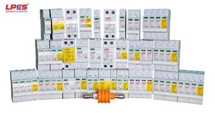
Every conductor, clamp, electrode and SPD carries an LPES part code, a datasheet and a type-test report. What is on the BOQ is what arrives at site, in the series you chose.
1,065+ products across three families
LPES BASIC, SMART, PRO and CENTURY series
Built and comply to IEC 62561 and IEC 61643
An earth grid copied from the last project will not suit this one. We measure soil resistivity, calculate the fault duty and size the grid, the conductors and the joints for your site.
Soil resistivity survey, Wenner four-pole
Grid design to IEEE 80 and IS 3043:2026
Protective earthing conductors per CEA 2023
Engineering from Gurugram and Budapest, with projects supplied across India, the Middle East, Africa and Europe. One catalogue and one set of standards wherever the site is.
IS and IEC on every document
Corporate addresses in Asia and Europe
Export packing and documentation
Products
LPES components, under the system
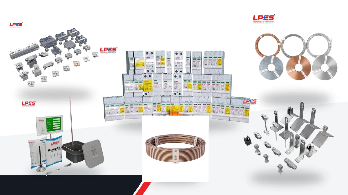
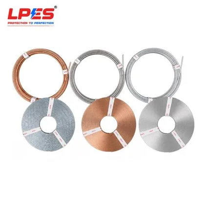
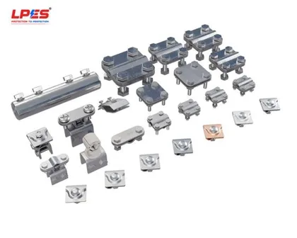
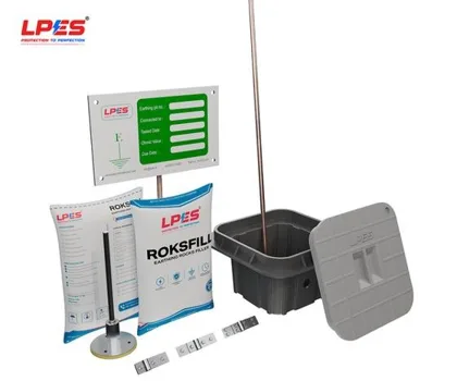
Every item carries an LPES part code, a datasheet and the standard it is built to. Four series by duty and budget: LPES BASIC, LPES SMART, LPES PRO and LPES CENTURY.
Enter the size of your building and the lightning activity where it stands. The calculator shows how often it should expect a direct strike. A Protection Review turns that first estimate into a protection level for your site.
Expected direct strikes to this structure
0.20 per year
About one direct strike every 5 years.
Collection area
25,321 m²
Flash density
8 per km² a year
A strike is likely within a few years. A full risk assessment will set the protection level.
First estimate: ND = NG × AD × CD × 10⁻⁶, using the collection area of IEC 62305-2. The detailed assessment adds the contents, the incoming services and the loss factors.
After handover
Protection that is kept, not only installed
LPES stays with the facility across four phases.
Before installationSite surveys, risk assessments, compliance reviews, specialist studies, engineering designs and specifications.
During deliveryLPES-manufactured and application-matched products, technical submittals, supervision, quality checks and deviation control.
At handoverInspection and test records, calculations, as-built drawings, acceptance evidence and recorded outstanding actions.
Through operationPeriodic inspections, maintenance support, reviews after an event or a modification, and updated protection records.
Next step
Bring your electrical protection together.
Understand your risks. Coordinate your protection. Know who owns each responsibility. Talk to LPES about a coordinated assessment, from Lightning to Load.
You sendSingle-line diagram, site layout, earthing and LPS drawings if you have them, and any failure history.
LPES reviewsAn engineer checks the four pillars and the interfaces between them against the standards that apply to your site.
You get:A written list of gaps, a recommended scope with responsibilities, and the next step, whether that is a survey, a study or a quotation.